Public Sector Solution
Fire Drill Route Recording
Record participant routes and checkpoint arrival times to evaluate drill performance with objective data.

Record checkpoint arrival times, drill duration, and movement routes
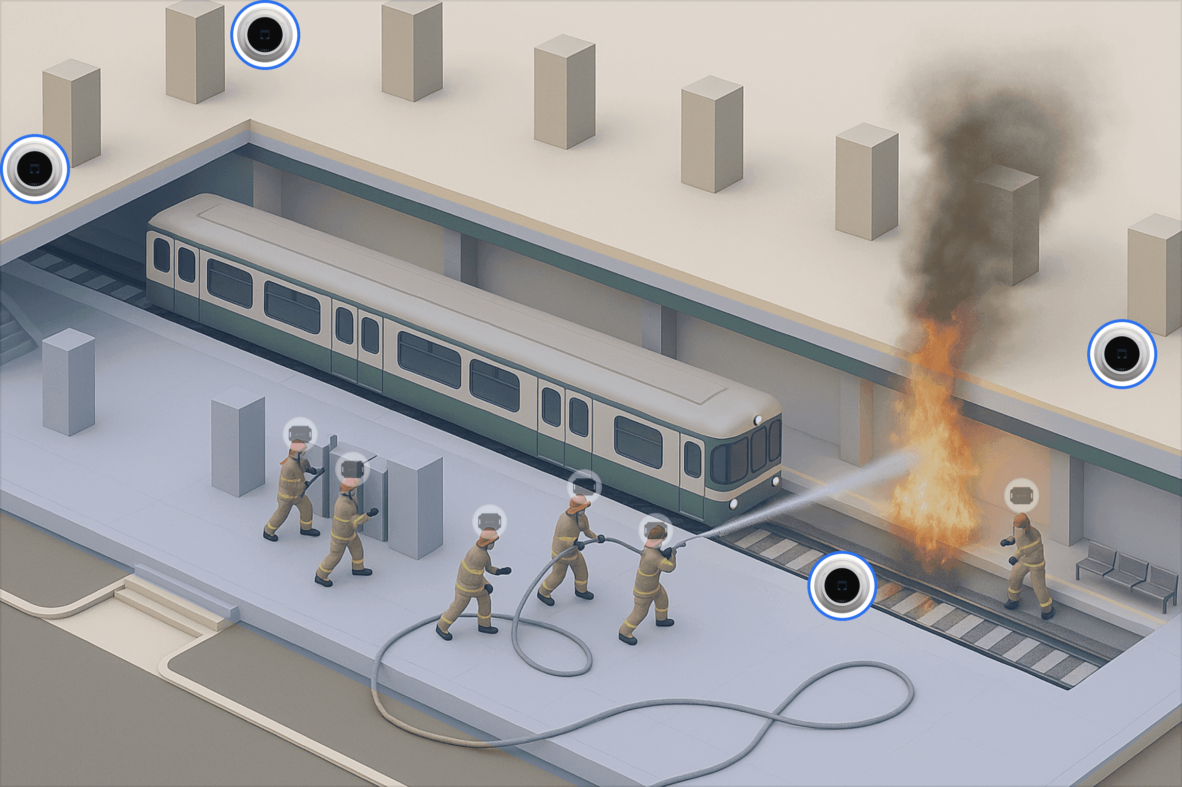
Crew members wear a UWB Tag, and TwinTracker UWB is installed on the training tower and mock structures. Entry time and arrival time at each section are recorded, leaving an individual route for each person. Radio conditions differ between outdoor areas and the inside of the tower, so receiver quantities are calculated section by section.
TwinTracker UWB
The reader installed across the training area to determine crew positions. An open outdoor course, the inside of a training tower and an underground mock structure have completely different radio conditions, so each section is designed separately. Deciding first whether evaluation needs floor level, zone level or coordinates for each section means the whole ground does not have to be covered at the same density, and metal and concrete sections go through verification in advance.









Checkpoint Arrival Time Recording
Crew movement paths and arrival times at each section are recorded, and the number entering and remaining is checked during the drill. Records by team and round serve as material for comparison against the evaluation criteria the instructor sets.
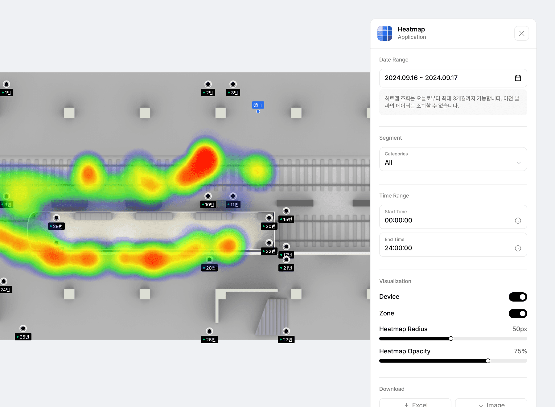
Heatmap of training movement
Once the drill ends, the areas where crews actually spent time appear in color. Which zones drew people and which nobody passed through shows in a single image, so the debrief runs on a screen rather than on memory and impressions. Overlaying rounds also shows whether the same zone stays empty every time.
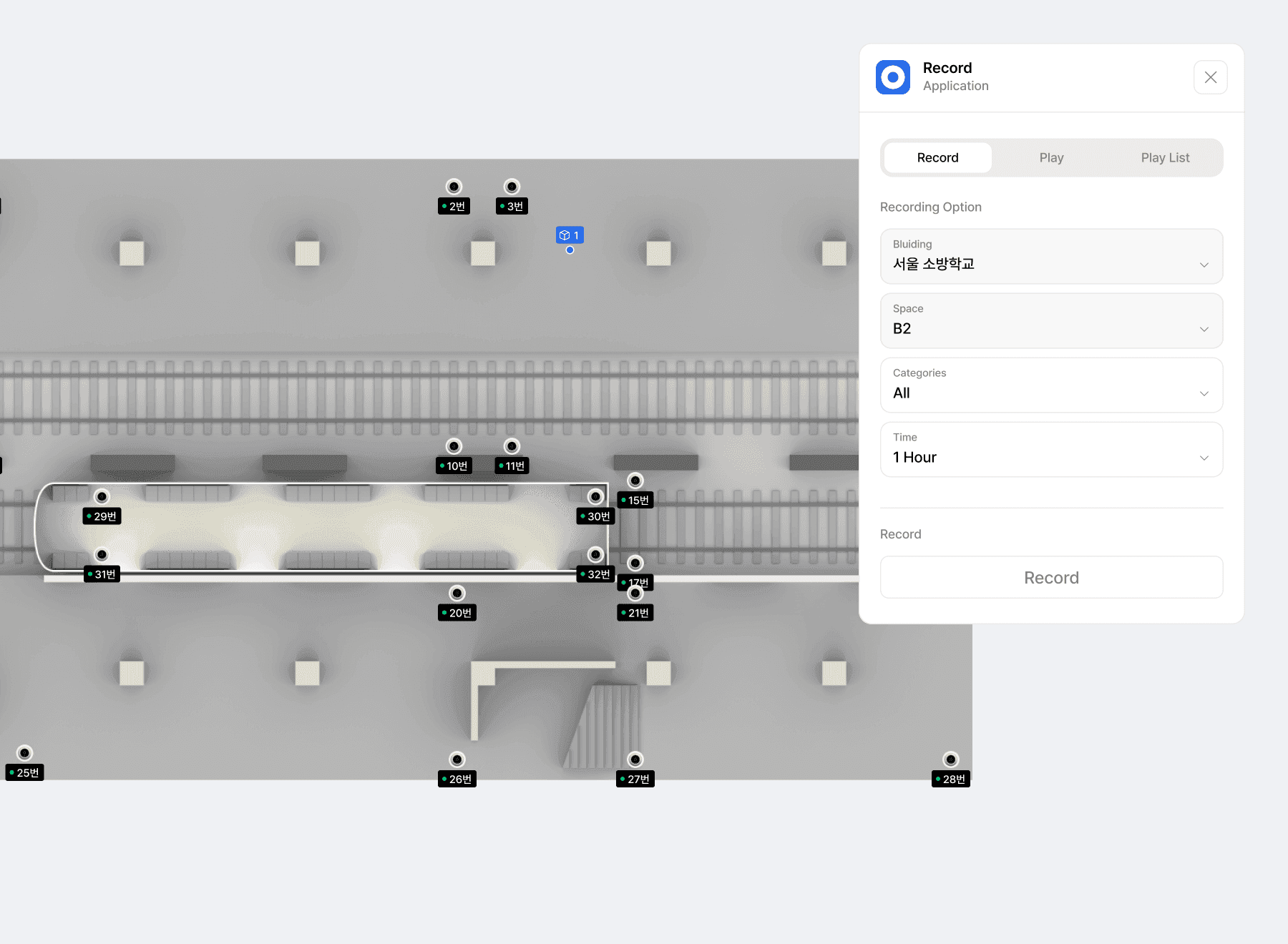
Individual routes examined in detail
Each crew member's route is retraced in time order. Entry time, arrival time at each section and dwell time remain together, narrowing down where the delay happened section by section. Laid out round by round, whether repeated training actually shortened the time shows in numbers, and that material goes straight into the evaluation report.
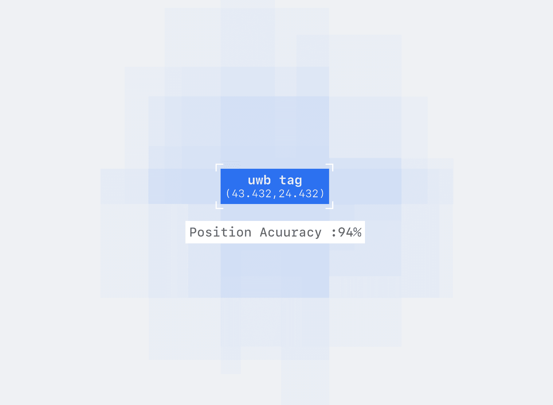
Floor and zone position on the training ground
Check which floor and zone each crew member is in during the drill. Position is calculated from tag signals collected by TwinTracker UWB and shown on a plan that reflects the training ground structure. Receiver placement and obstruction by structures set how finely positions can be separated.
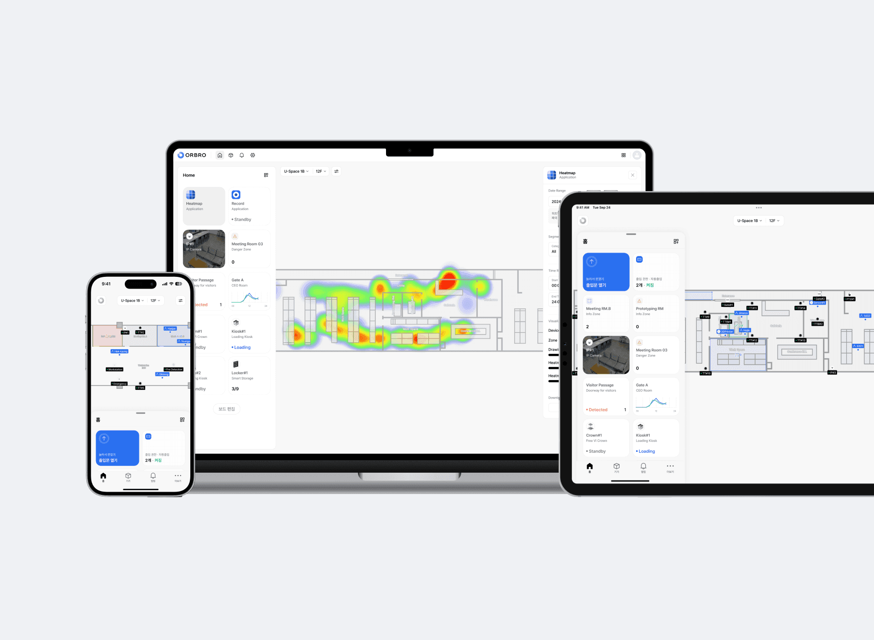
Live monitoring while the drill runs
While the drill is under way, the screen shows which crew member is in which zone. The controller gives directions from the screen instead of asking for positions over the radio, and checks how many have entered and who has not come out yet. Headcount per zone is shown alongside, so a crowd building up in one section is visible as it happens.
Location monitoring across the training ground
Crew positions are checked on a plan that reflects the training ground structure. Receiver and tag placement and signal reception are managed to run monitoring across the training area.
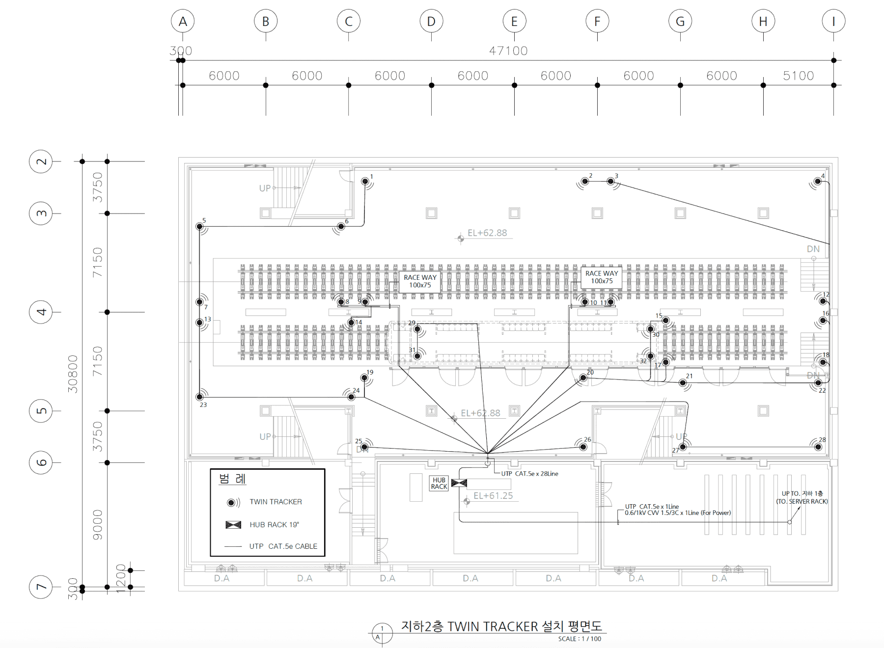
Installation designed on the site drawing
A floor plan marking TwinTracker UWB mounting points and cable routes on the training ground drawing comes first. Because the quantity needed changes with stairwells and pillar positions, the configuration and construction scope are fixed at the drawing stage and the quote is calculated from there. If the training layout changes, the equipment can be moved to cover a different area.
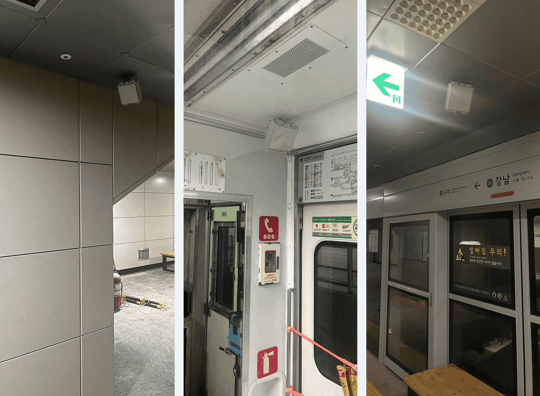
On-site installation and tag reception
Receivers mount on the drill tower and mock structures to pick up signals from the tags crews wear. Because the facility stays in service, they are mounted in a way that minimizes drilling and cabling, and the tag mounting method is decided against both wearing over turnout gear and withstanding impact during the drill. Sections where the signal dropped are listed so they can be reinforced before the next round.
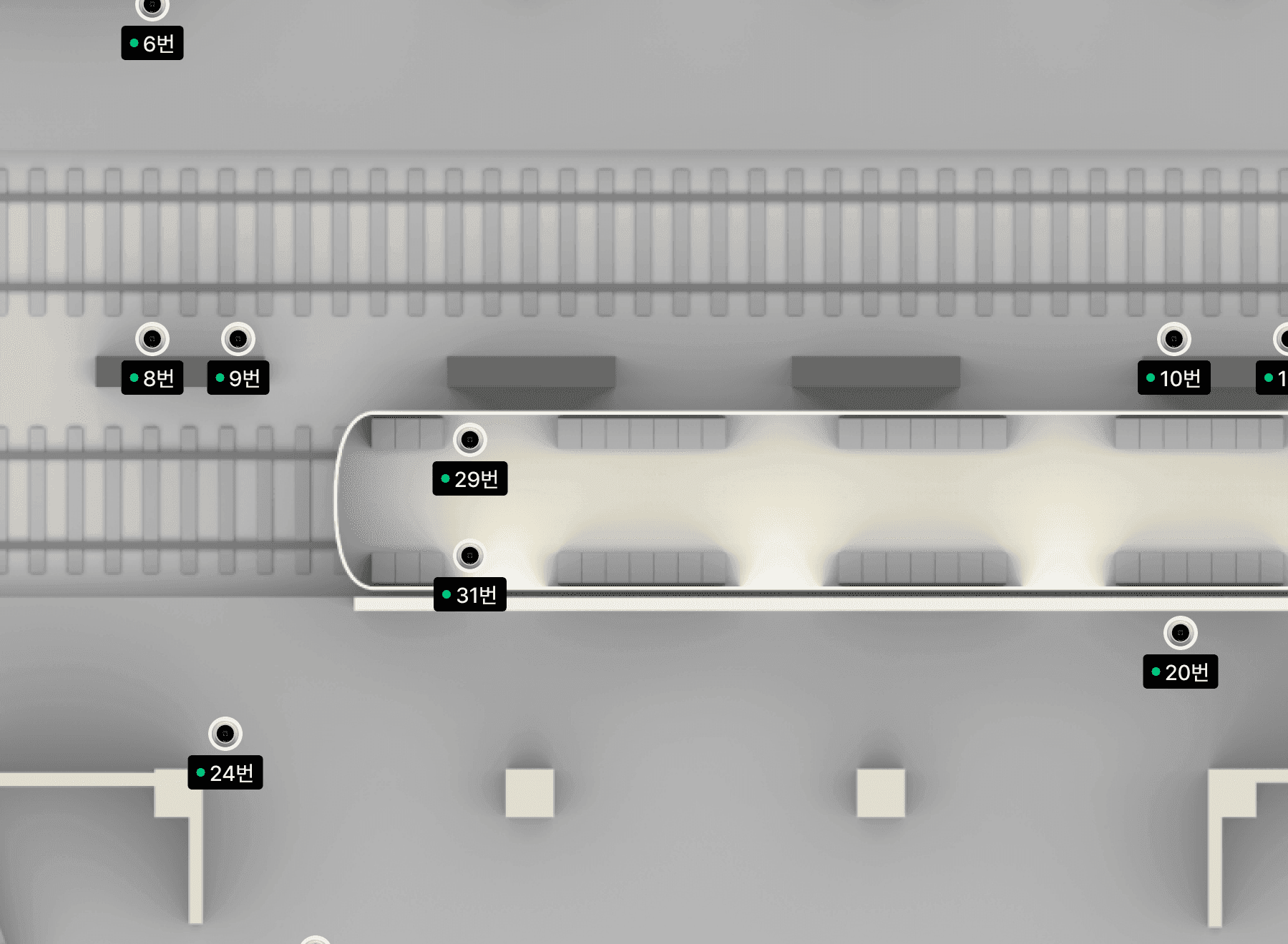
A view that mirrors the training ground
Positions are checked on a view that reproduces the floors, stairs and approach routes of the training ground. Plane coordinates alone do not convey which floor or which section, so only a view that reflects the real structure lets the controller judge at a glance. When structures are moved or the training layout changes, the view is updated with them.
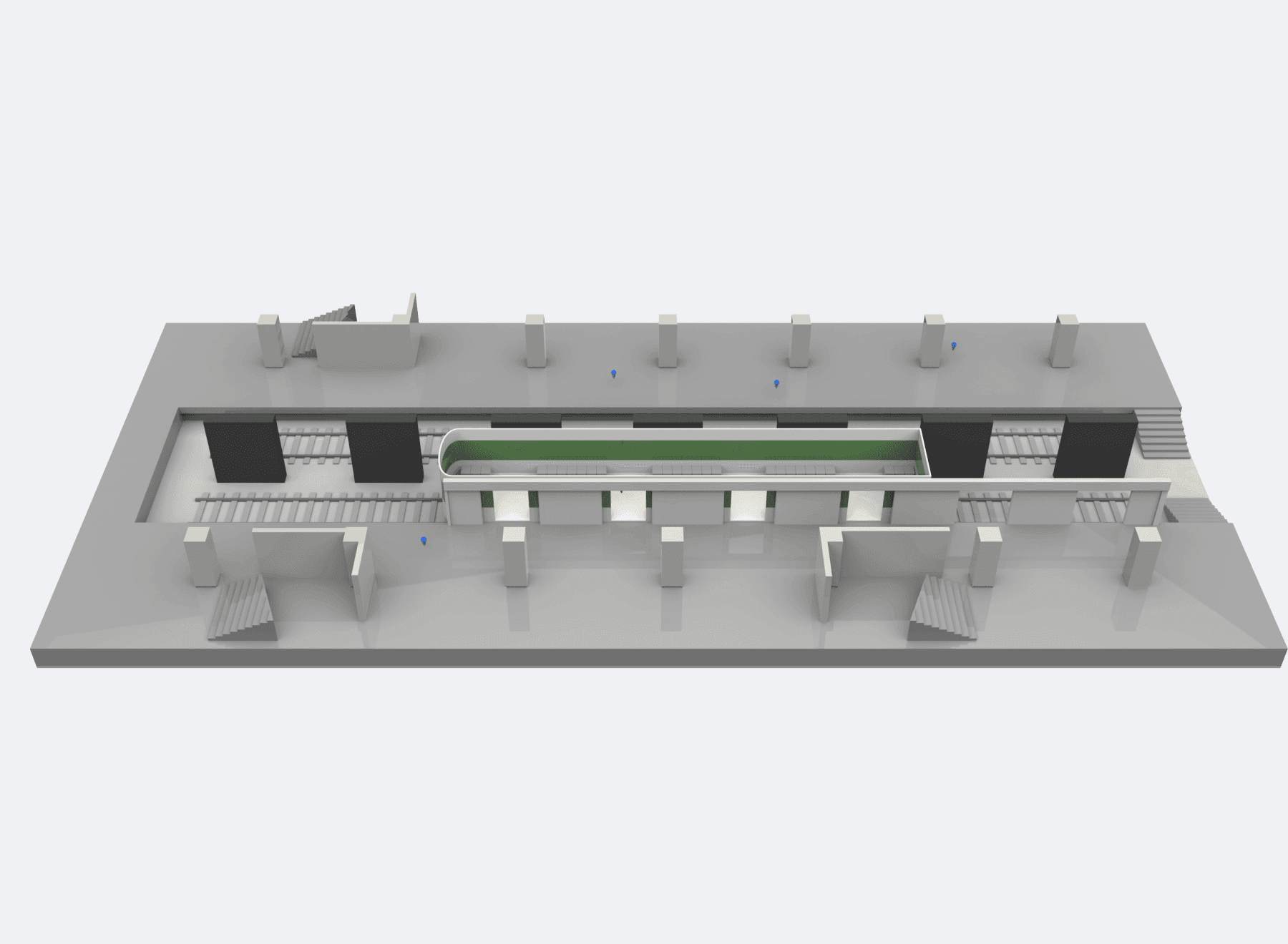
From installation drawing to 3D view
Architectural drawings are used to build the training ground as a three-dimensional view with positions placed on top. Where floors overlap, a plan alone does not read, so both a floor-by-floor view and a whole-site view are provided. Deployment and operation stay inside the organization's internal network and training records never leave it.
Recommended Products
Components Based on ORBRO OS
Each solution operates with various products connected on top of ORBRO OS. Configurations can be flexibly adjusted depending on the scope of application and on-site conditions.
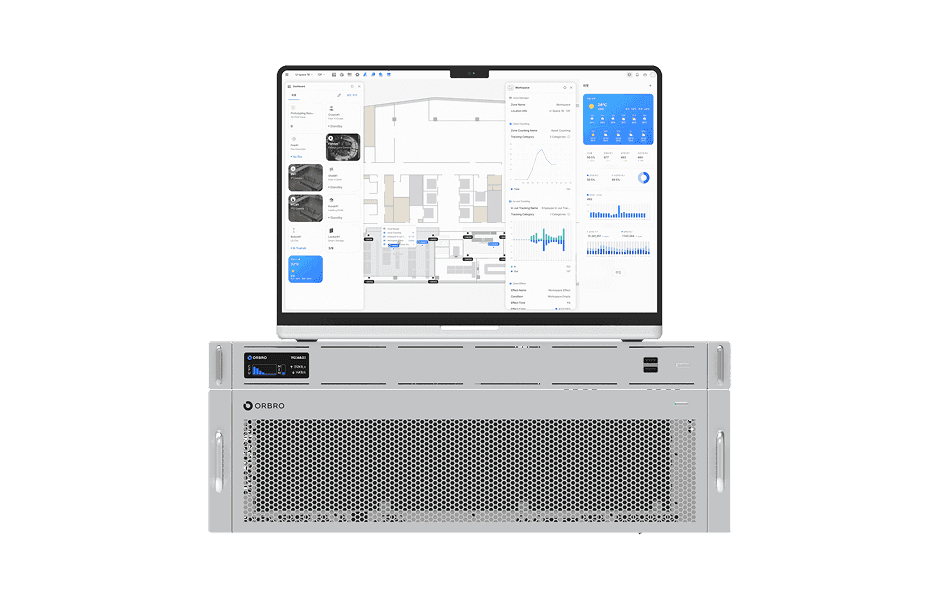
ORBRO OS2
ORBRO OS2
Align location, video, and sensor data on a spatial layer to turn all on-site situations into a single operational workflow.
Learn More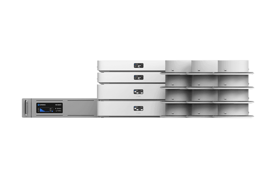
UWB Location Tracking
UWB Location Tracking
Enhance worker safety and precisely manage the movement of assets and equipment through real-time tracking, improving productivity and operational efficiency at the same time.
Learn More