Manufacturing Solution
Forklift–AMR Collision Avoidance
Manage risk-response records for areas where forklifts and AMRs operate together under one consistent standard. Repeated test results can support production-line expansion and operational reviews.

Provide forklift coordinates to the AMR control system for avoidance decisions
TwinTracker UWB receives signals from forklift-mounted UWB Tags, and ORBRO Server converts them into factory coordinates. Coordinates are delivered to the AMR control system with timestamps and validity status. Receiver placement and coordinate-conversion rules are defined by surveying racks, equipment, and crossing aisles.
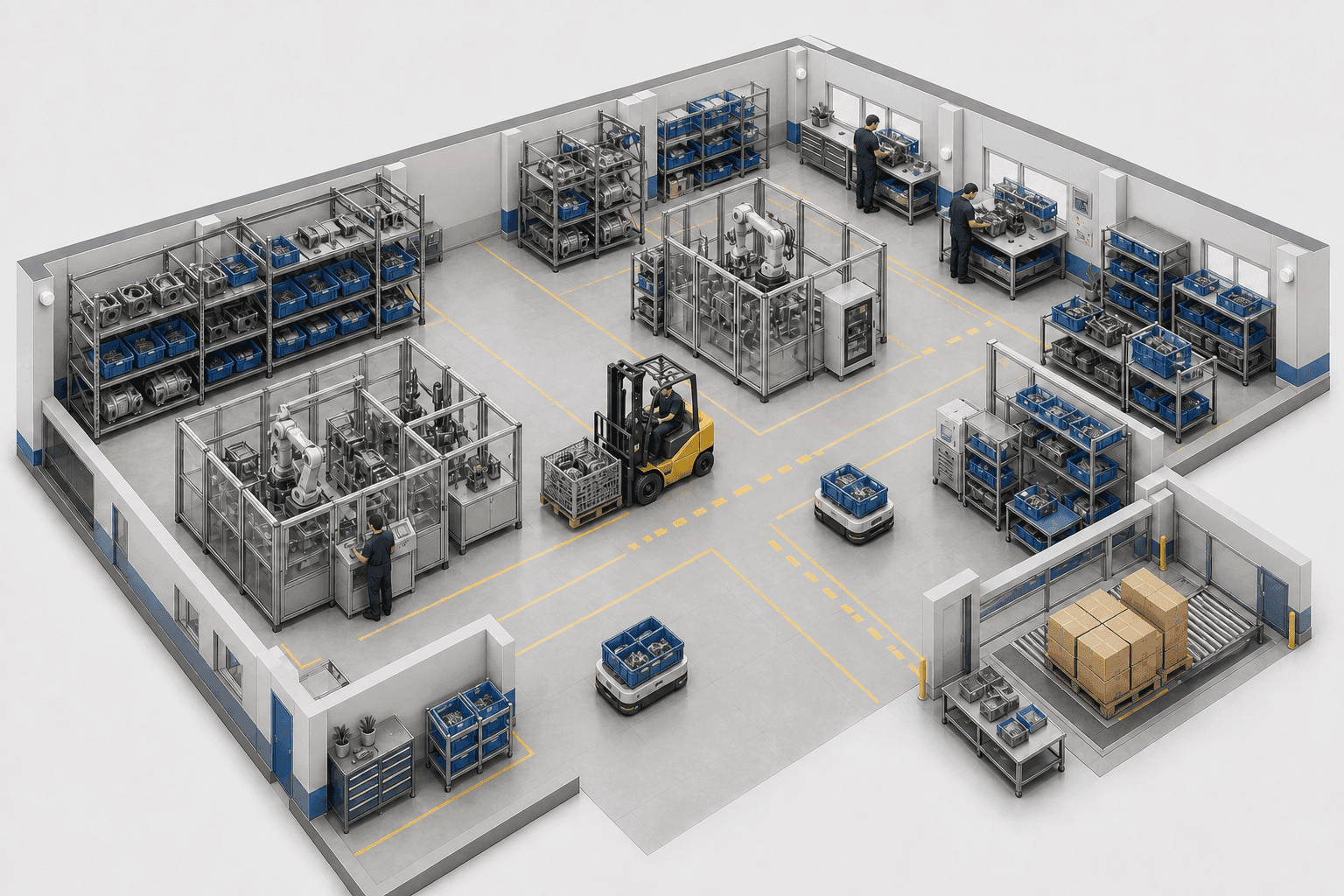

TwinTracker UWB
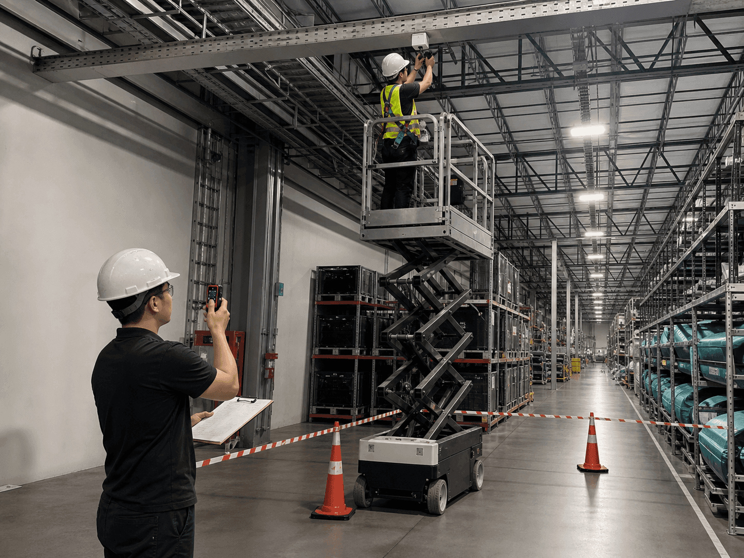
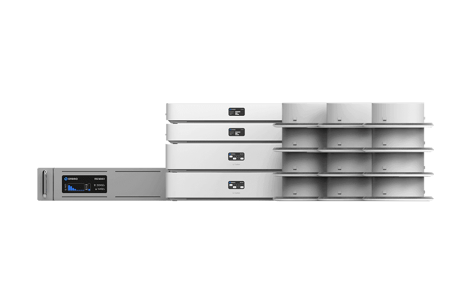
A UWB receiver installed on factory H-beams and above aisles to receive forklift tag signals. Its height and direction are set to cover rack ends and AMR crossing zones first. Signal coverage and coordinate continuity are verified with actual equipment and loads in place.








Coordinate-Based Forklift Avoidance Integration
Mount a UWB Tag on each forklift and calculate its movement coordinates against the factory map. Measurement time and validity status are sent to the AMR control system to support slowdown and stop decisions.
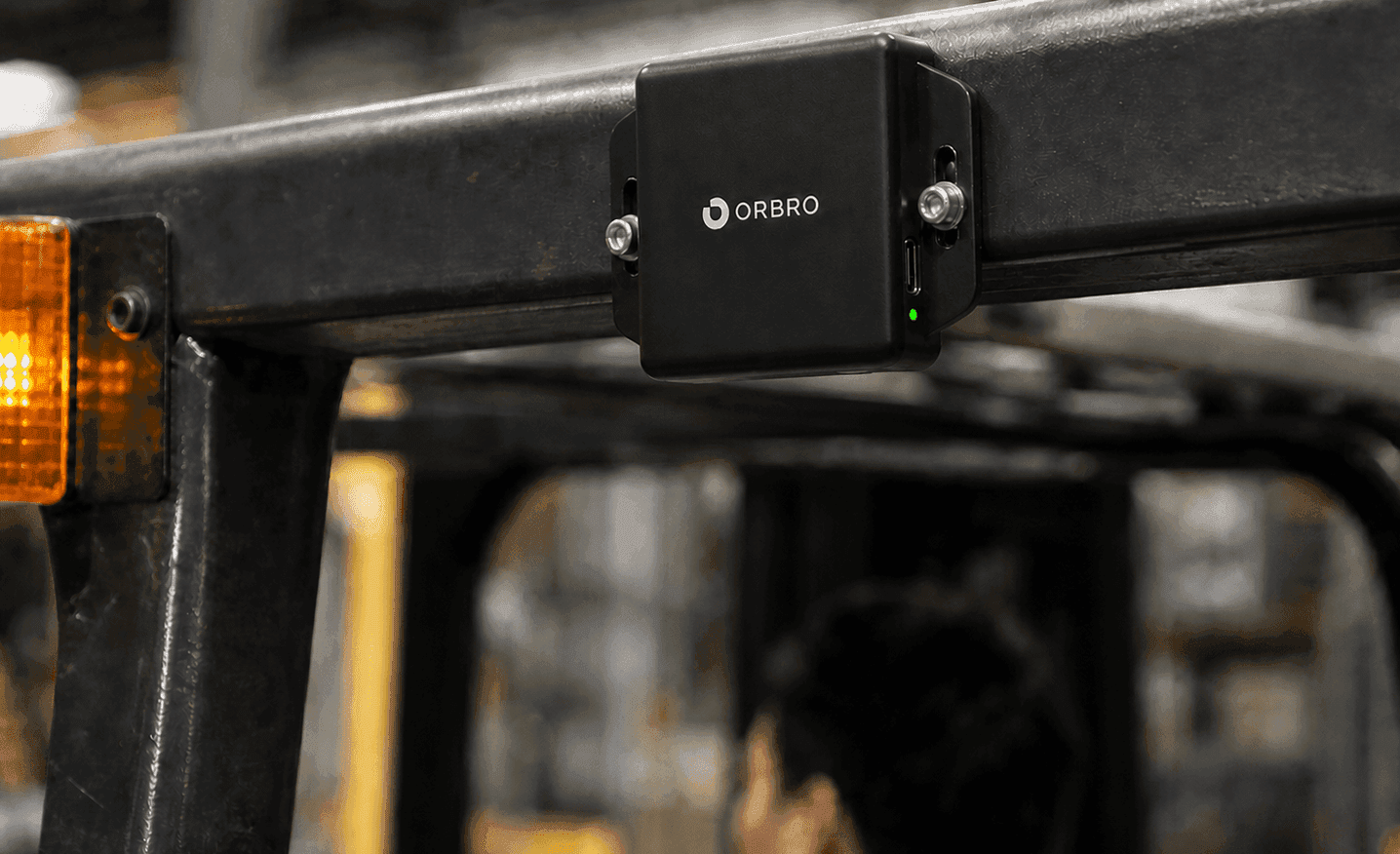
Install UWB Tags on Forklifts
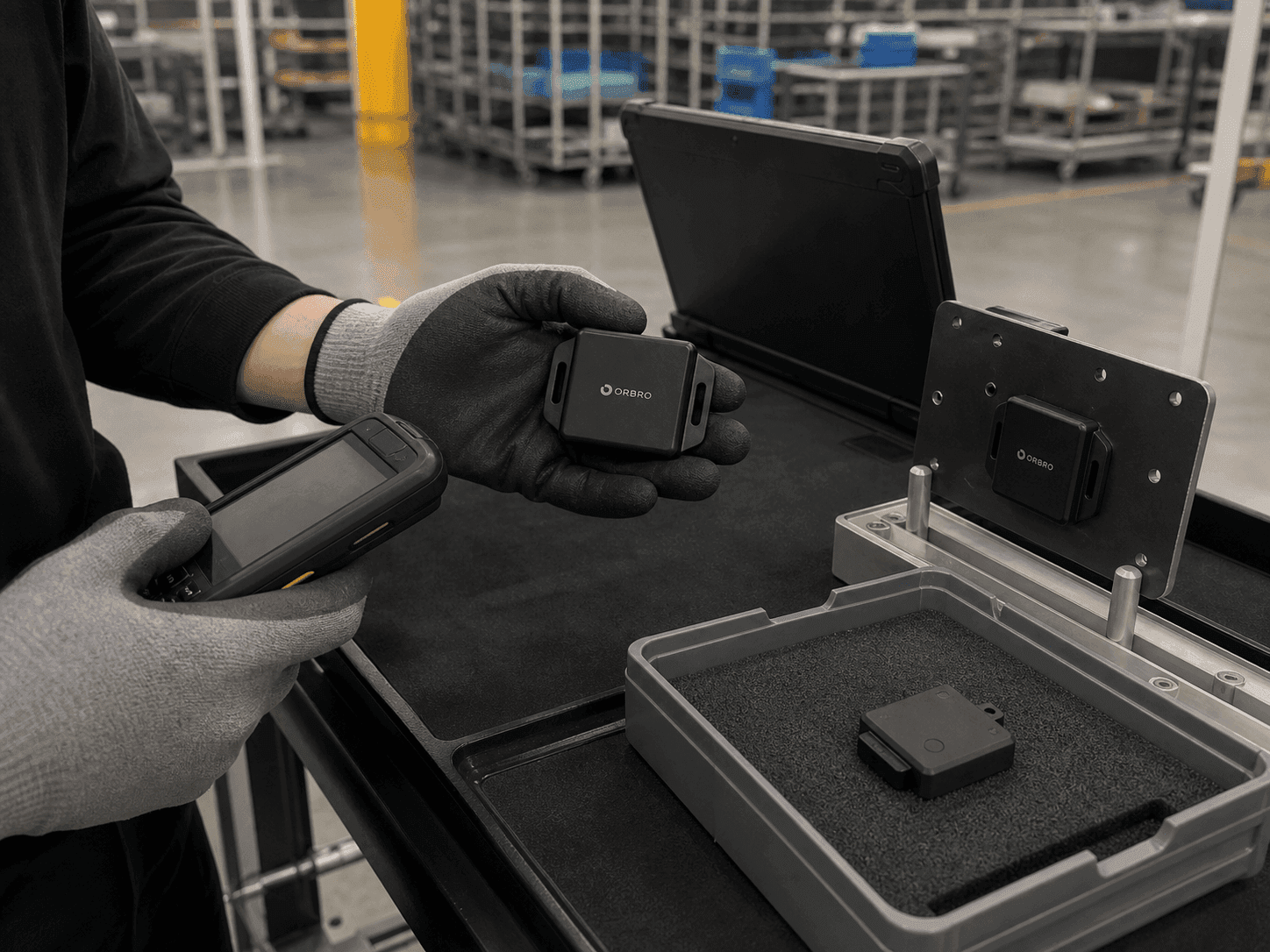
Install a UWB Tag RU-O3405 on the forklift's overhead guard. The 66 × 50 × 20 mm tag uses mounting wings on both sides to withstand vibration. Review the mounting position and power method after checking mast obstruction, shift duration, and maintenance routes.
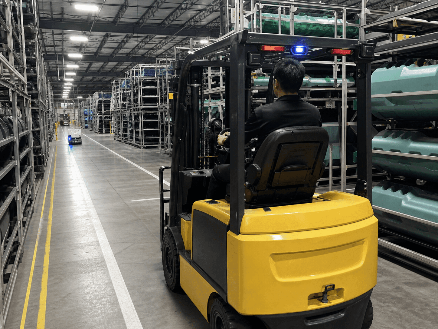
Continuously Track Forklift Positions
Continuously collect tag coordinates while forklifts travel through factory aisles. ORBRO Server stores the forklift ID, position, and measurement time in one record. Coordinate update rules reflect vehicle speed, aisle width, and operating standards for crossing zones.
Align Coordinates with the Factory Map
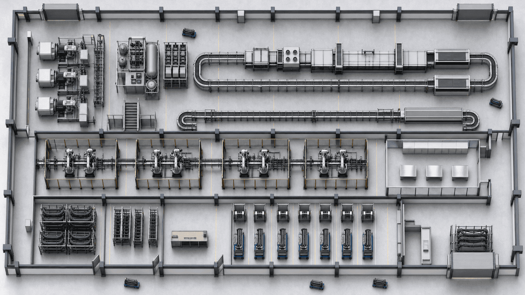
Using the factory layout as the common reference, the origin and axis directions of the UWB coordinates and the AMR map coordinates are aligned. Main aisles and control points are surveyed on site to set the coordinate transformation values, and calibration is repeated when production lines or rack layouts change.
Integrate AMR Slowdown and Stop Decisions
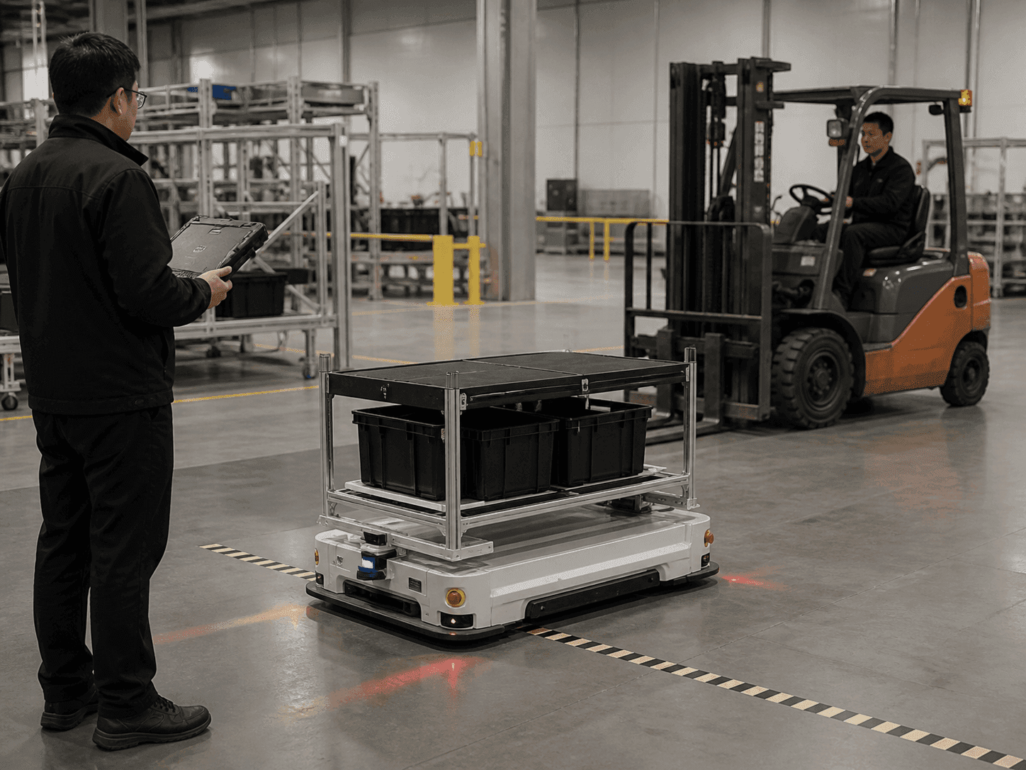
Send the forklift ID, coordinates, measurement time, and validity status to the AMR control system. The AMR compares its current route with the forklift's approaching position to decide whether to slow down, stop, or reroute. Behavior during communication loss or delayed coordinates is defined with the AMR manufacturer.
Validate Onsite Positioning Quality
Blind spots and receiver mounting points are surveyed, and external tags and stale coordinates are separated out. Repeated driving tests confirm coordinate delivery and AMR response conditions and leave them as operating criteria.
Address Blind Intersections Before Line-of-Sight Detection
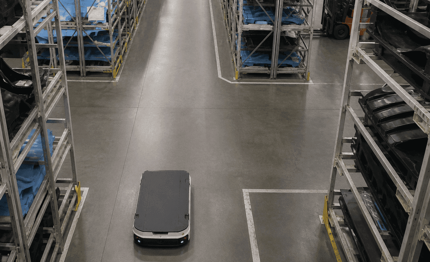
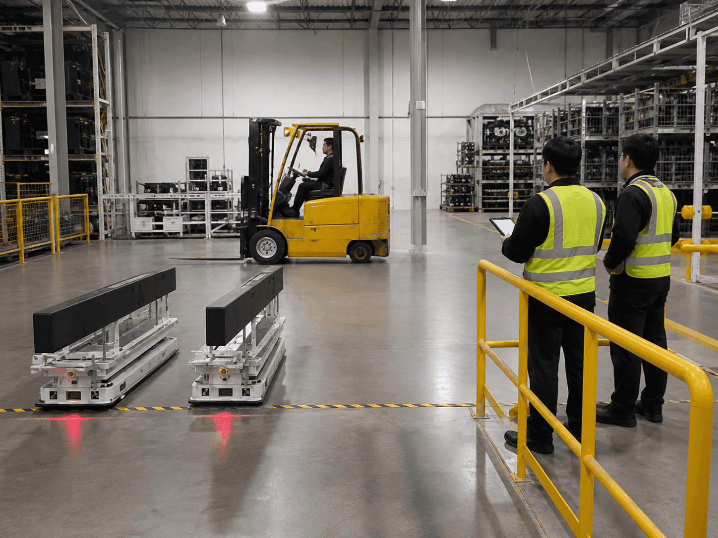
Prioritize crossing aisles where high racks and equipment block visibility. The AMR can identify an approaching forklift from transmitted coordinates before it appears on the robot's own LiDAR. Use aisle width and vehicle speed limits to configure waiting and slowdown zones.
Survey Receiver Locations on Factory Structures
Measure the spacing and height of receiver mounting structures for each zone. Use these measurements to calibrate TwinTracker UWB installation coordinates and compare position deviations by aisle. Repeatedly verify coordinate continuity under operating conditions with equipment and loads in place.
Check Registered Tags and Coordinate Quality
Separate the signals of registered forklift tags from external tags. The location data ORBRO provides and the AMR control system's decision to use those coordinates are connected under the integration protocol. Set how last-received time and coordinate validity status are handled, then check behavior before and after the change.
Validate Avoidance Scenarios in Operation
Test normal passage, intersecting approaches, emergency stops, and communication-loss scenarios separately. Record coordinate-delivery status and whether the AMR slowed, stopped, or rerouted in each scenario. Test history can inform receiver placement and integration rules for the next production line.
Recommended Products
Components Based on ORBRO OS
Each solution operates with various products connected on top of ORBRO OS. Configurations can be flexibly adjusted depending on the scope of application and on-site conditions.
UWB Location Tracking
UWB Location Tracking
Enhance worker safety and precisely manage the movement of assets and equipment through real-time tracking, improving productivity and operational efficiency at the same time.
Learn More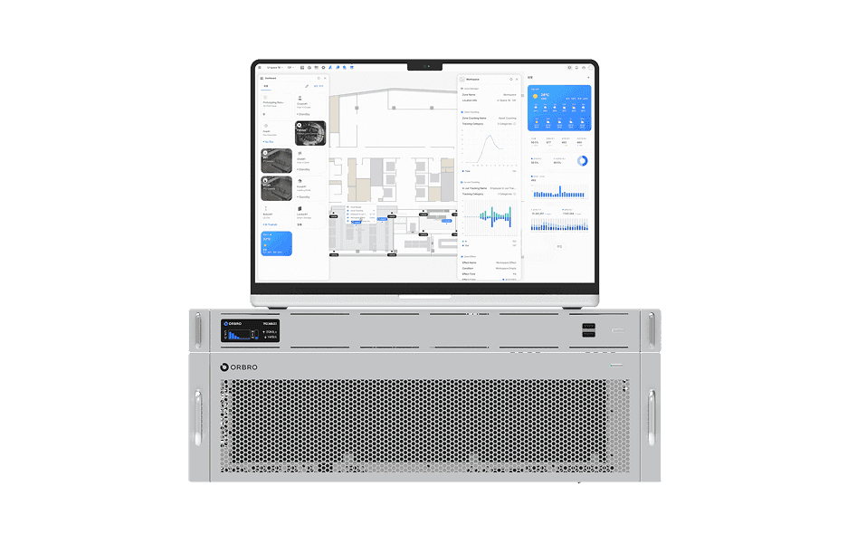
ORBRO OS2
ORBRO OS2
Align location, video, and sensor data on a spatial layer to turn all on-site situations into a single operational workflow.
Learn More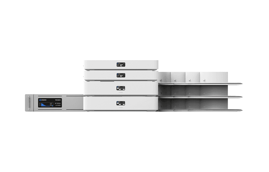
AoA Location Tracking
AoA Location Tracking
Beyond simple coordinates, this solution leverages signal angles to precisely identify movement direction and paths. It supports access control, enhanced security, and customer flow analysis as a next-generation RTLS solution.
Learn More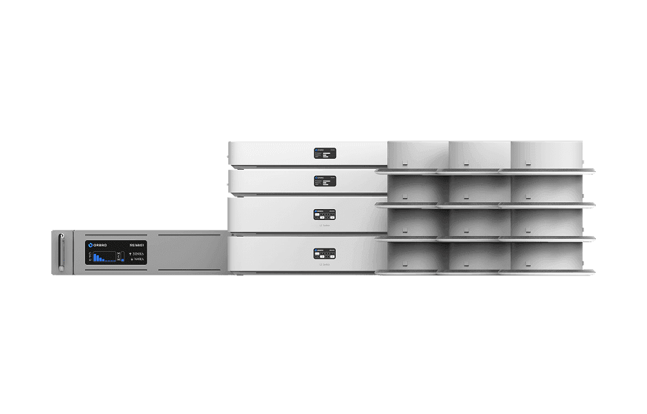
BLE Location Tracking
BLE Location Tracking
BLE is an optimal technology for managing large-scale assets simultaneously at low cost. It enables real-time monitoring of thousands of assets, supporting efficient operations and cost reduction.
Learn More