Forklift Collision Avoidance When AMRs Share the Aisle: Pass UWB Coordinates, Let the Robot Decide
2026-09-16
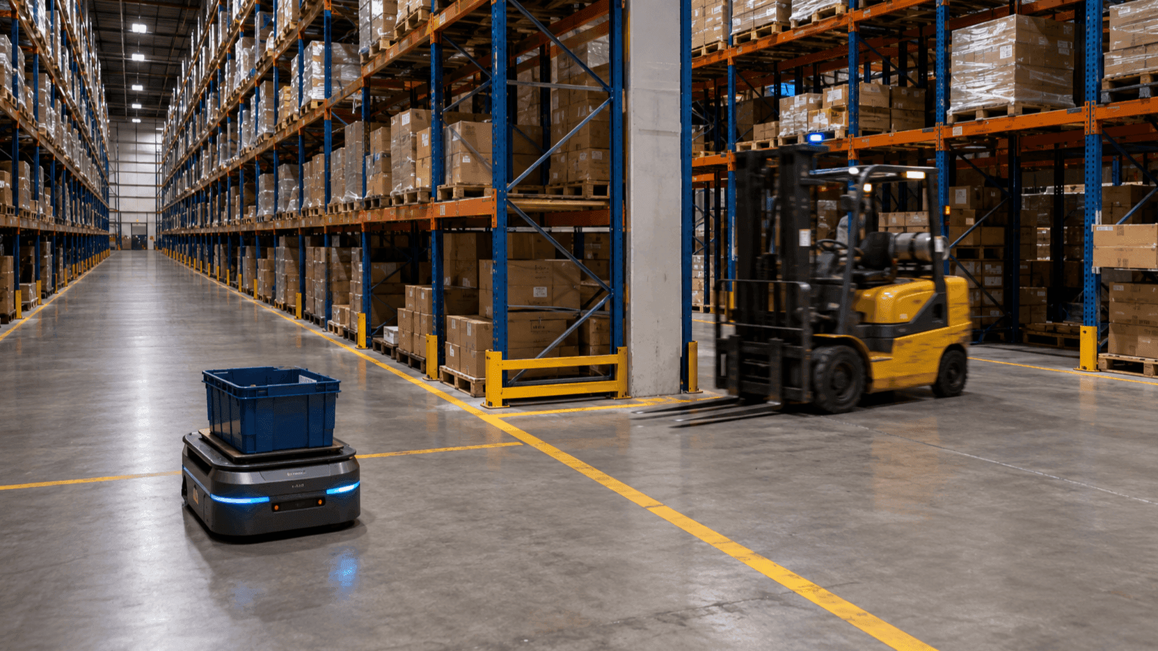
Picture the spot where forklift collision avoidance is decided: the end of an aisle where the racks rise about 6 meters, at a T-shaped intersection. From one side, an AMR carrying a tote approaches along its planned route. From the other, a forklift with a pallet raised comes around the end of the rack. Neither can see the other yet, because the rack blocks the line of sight. The AMR's lidar picks up the forklift only after its front wheels have entered the intersection, and if deceleration starts then, only a few meters remain.
As more factories bring in AMRs and run a mixed fleet, this scene has become a new problem. When only forklifts used the aisles, drivers negotiated intersections with a horn and eye contact. An AMR cannot hear a horn or read a glance. It avoids only what its own sensors detect. That is why someone at the line-expansion meeting proposes separating AMR zones from forklift zones entirely, and in a section with only one aisle, that is simply not possible.
The inquiries we receive have almost the same shape. Can the forklift's position be received as real-time coordinates and used to control the AMR? Can the positions of people and material-handling equipment be seen together in a higher-level system so their movements can be coordinated? This article lays out the forklift collision avoidance structure that answers those questions. The gist is one line: pass the forklift's coordinates to the AMR, but leave the decision of whether to avoid it to the AMR.
I. Lidar Only Avoids What It Can See
"The AMR has lidar, so doesn't it avoid obstacles on its own?" This is the first objection raised in most forklift collision avoidance evaluations, and it is half right. Lidar accurately detects obstacles within its field of view, and the AMR stops or detours in front of them. The problem is the field of view. Lidar sees only as far as light travels in a straight line. A forklift coming around the end of a rack is an object that does not exist while the rack hides it, and an object that appears out of nowhere the moment it clears the rack.
The forklift has its own constraints. With a pallet raised, its braking distance grows with the load weight, and the mast blocks the driver's view. If, by the time the lidar sees the forklift, both the AMR and the forklift are already inside the hard-braking zone, the only option left is an emergency stop. An emergency stop prevents the collision, but the load shifts, and if it happens repeatedly, the AMR's entire operating schedule slows down.
So what is needed is not a better lidar but forklift proximity detection that tells the AMR about the approach before it becomes visible to lidar. If the AMR knows in advance that a forklift is coming down an aisle 15 meters from the intersection, and at what speed, it can respond with deceleration and a wait before entry instead of an emergency stop.
In an earlier article, Robots Know Where They Are, but Not Where People Are, we covered giving people tags and placing them on the robot's map. This article goes in the opposite direction. We attach a tag to the forklift and pass its coordinates to the AMR control system.
II. UWB Forklift Tracking Passes the Coordinates, but the AMR Decides
The structure has four steps, starting with UWB forklift tracking. A UWB tag fixed to the forklift transmits a signal, and TwinTracker UWB units mounted above the aisle receive it. ORBRO Server calculates the coordinates from the differences in arrival time and converts them into a position on the factory floor plan. It then bundles the forklift ID, coordinates, measurement time, and validity status and delivers them to the AMR control system.
Here we draw a line. What is delivered is a coordinate, not a command. Whether to slow down, stop, or detour is decided by the AMR control system, which compares its own route with the forklift's approach position. There are two reasons. First, the AMR is the one that knows its route, its load state, and its braking characteristics. Second, the AMR already has its own safety sensors and safety-rated functions, and the coordinates coming from the higher-level system do not replace those AMR safety functions; they are supplementary information that arrives earlier. Even if the coordinates drop out, the lidar keeps running.
For the same reason, we do not decide how the AMR should behave when communication is lost or coordinates arrive late. We define it together with the AMR manufacturer. How many seconds the last coordinate can be trusted, and whether the AMR should then wait before the intersection or proceed on lidar alone, are questions that belong to the robot's operating rules.
Attaching the measurement time and validity status to each coordinate follows the same logic. With only a coordinate, the AMR cannot tell whether the value is from just now or from 3 seconds ago. The timestamp is what allows stale values to be discarded, and the validity status is what allows values with poor reception quality to be excluded from the control input.
III. The Two Maps Must Share an Origin
There is a problem to solve before coordinates can be passed. The coordinates calculated by UWB and the map coordinates used by the AMR must share the same origin and the same axis directions. If each system keeps its own origin, the same forklift shows up in the wrong aisle on the AMR's map.
So the factory floor plan becomes the common reference. A few key aisles and reference points are measured directly on site, and those values are used to define the transformation that converts UWB coordinates into AMR map coordinates. When a production line or rack layout changes, this transformation must be re-established. If the layout has changed but the transformation has not, the coordinates are correct while the map is wrong.
Receiver placement follows the same logic as line of sight. TwinTracker UWB units are installed on the factory's H-beams and above the aisles, with height and orientation chosen to cover the rack ends and AMR crossing zones first. A reception range measured in an empty factory without equipment or stored goods cannot be trusted. In actual operating conditions, with equipment and pallets in place, we check aisle by aisle that the forklift's coordinates remain continuous without dropping out.
The tag is mounted on the forklift's overhead guard. The UWB Tag RU-O3405 measures 66×50×20mm and is fixed with mounting wings on both sides so that it withstands vibration. When choosing the mounting position, we first check whether the mast blocks the signal, how power will be maintained across shift changes, and whether the tag gets in the way of maintenance routes. If a single tag is mounted incorrectly, that forklift disappears from the map, and the AMR is back to handling it with lidar alone.
IV. Test Forklift Collision Avoidance in Four Situations Separately
Whether the integration works cannot be confirmed by passing through once. Under normal conditions, any configuration runs fine. The difference shows up when conditions are not normal. So we divide the situations into four, test them repeatedly, and record the coordinate delivery status and the AMR's result together in every test.
| Scenario | Coordinate delivery status | Expected AMR behavior | What to record |
|---|---|---|---|
| Normal pass | Forklift coordinates updating normally | Recognizes the approach early, decelerates, resumes after passing | Distance at which deceleration starts, time to pass |
| Crossing approach | Both approach the intersection at the same time | Waits before entry or detours | Waiting position, time of restart |
| Emergency stop | Forklift accelerates sharply just before the intersection | Stops | Time to stop, load condition |
| Communication loss | Coordinate reception interrupted or delayed | Behavior defined with the manufacturer (wait, or pass on lidar alone) | Time of last coordinate, time of recovery |
The fourth row has no single correct answer. That cell is filled in together with the AMR manufacturer, and only after it is filled does the integration go into operation.
Testing also includes filtering. We distinguish registered forklift tags from signals coming in from other zones, and exclude from the control input any values with low coordinate quality or a stale last-reception time. When the filter is changed, we compare before and after to confirm that outside tags are filtered out while legitimate targets remain. If the filter is too strict, the forklifts that actually matter drop out; if it is too loose, the AMR stops because of a forklift in the next zone.
Test records are not discarded. If there is a record of how early deceleration started at which intersection under which conditions, that record becomes the basis for deciding receiver placement and integration conditions on the next production line.
V. Deployment Considerations for a Mixed Fleet
- Decide which intersection to start with. Crossing aisles where tall racks and equipment block the line of sight come first. Set the pre-entry waiting zone and the deceleration decision zone based on aisle width and the vehicle speed limit.
- Match the coordinate update conditions to operating requirements. The faster the vehicles and the narrower the aisle, the more frequent the updates need to be.
- Make a list of the items to define with the AMR manufacturer: input format, allowable latency, behavior on communication loss, and the criteria for validity status. Without this list, operation starts with the fourth row of the test table still empty.
- Put forklift tag power and inspection into the operating procedure. A single line in the procedure to check tag status at shift change is what prevents forklifts from disappearing from the map.
- Schedule recalibration whenever the layout changes. If re-verifying the coordinate transformation is one item in the plan for any rack relocation work, the AMR will not stop in the wrong aisle the day after the work.
Closing
In a factory where AMRs and forklifts share the same aisles, forklift collision avoidance comes not from a more sensitive sensor but from information that arrives before anything becomes visible. Capture the forklift's coordinates and pass them to the AMR, leave the decision to the AMR, and test the four abnormal situations in advance. That is the whole structure.
ORBRO provides this structure as one package. TwinTracker UWB receives the forklift's coordinates, ORBRO Server computes them in factory coordinates and passes them to the AMR control system, and the same coordinates appear on the floor plan in ORBRO OS as the positions of forklifts, AMRs, and people together. What a location tracking system consists of is covered in What Makes Up a UWB Location Tracking System, and how a camera detects collision risk between forklifts and people is covered in Forklift Collision Prevention with AI Camera Danger Zone Detection. The forklift and AMR collision avoidance configuration is laid out on the solution page. Tell us which intersection is the problem and which AMR manufacturer you use, and we will start the review from that section with you.
Recommended Blogs
RTLS Pilot Project: What Your Proof of Concept Should Verify
2026-09-15
Semiconductor Fab Personnel Tracking: Why Location Is Stored Only by Floor and Zone
2026-09-14

A New Era of Logistics: Smart Warehouse Management Powered by GPT-6 and Real-Time Positioning
2026-09-12
Patient Elopement Detection, Start With the Exit Routes, Not the Whole Ward
2026-09-11